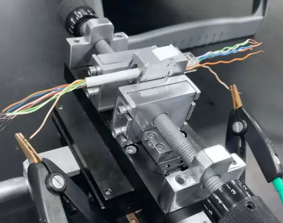
PoE Connector Arcing Test (Sparking Test)
The sparking test (also called arcing test) assesses the connector's ability to handle electrical arcs which might occur when connecting or disconnecting under load. An electrical arc is a visible glow discharge by the passage of electric current through gasses in the air. In the context of PoE, this can happen if a connector is unplugged while power is still being supplied. Such arcing can cause damage to the connector pins, degrade connector performance, and even present a fire risk in extreme cases. Therefore, the sparking test ensures that PoE connectors can withstand such events without failure.
What is PoE?
Power over Ethernet (PoE) is a technology that allows electrical power and data to be transmitted over 2 pairs (IEEE 802.3at Type 1 PoE, Type 2 PoE+) or 4 pairs (IEEE 802.3bt Type 3 4PPoE or PoE++ & Type 4 4PPoE or PoE++) of a single Ethernet cable. It was developed to simplify the deployment of networked devices by eliminating the need for separate power cables, which can be particularly useful in scenarios where it's challenging or impractical to run both power and data cables to a device. It finds applications in various industries and settings, improving efficiency, flexibility, and ease of installation for a wide range of devices and systems. PoE is commonly used in various applications, primarily in the fields of networking, telecommunications, and security.

PoE Applications in Real Life
PoE simplifies installations in real-life applications of VoIP Phones in office environments, wireless access points (WAPs), Wi-Fi coverages in large buildings and outdoor settings without the need for a nearby power outlet, IP cameras and surveillance systems without separate power cables for each camera, energy-efficient PoE lighting in building automation systems, and programmable logic controllers (PLCs) for system monitoring and control in industrial automation.
Why PoE or 4PPoE Connectors Shall Comply With IEC60512-99-001/002
IEC60512-99-001/002 test methods simulate the real-life usage of the connectors on PoE switches. All PoE connectors shall comply with IEC60512-99-001 (test methods for IEEE 802.3at Type 1 PoE, Type 2 PoE+ connectors) or IEC60512-99-002 (test methods for IEEE 802.3bt Type 3 PoE++ or 4PPoE & Type 4 PoE++ or 4PPoE connectors). In practical application, when there is no patch cord inserted into the jack of the PoE switch, the PoE switch will not supply power. Once the jack is plugged in, the PoE switch detects the patch cord, then communicates with the device to determine which level of PoE it belongs to before supplying power. The PoE switch supplies the required amount of power through the PoE patch cords to the equipment. Up to now, there has been no spark generated. When the patch cord is unexpectedly removed from the PoE switch, the PoE switch still remains powered. Therefore, the moment the plug's contacts separate from the jack's pins, an electrical spark is produced.
PoE Connector Spark Test: ISO/IEC11801 and IEC60512-99
The ISO/IEC11801 standardizes the mechanical dimensions of the connectors and their transmission performances to ensure the reliability of the entire structured cabling system. Before testing the connectors for its PoE capability according to IEC60512-99-001/002, all RJ45 connectors are governed by the ISO/IEC11801 standard. So, the IEC60512-99-001 or IEC60512-99-002 standard compliances along with ISO/IEC11801 ensure that the transmission performance of the connectors will not be impacted by the use of PoE.
IEC60512-99-002 Ensures 4PPoE (PoE++) Connector Reliability and Safety
The IEC60512-99-002 simulates the real-life situation when the 4PPoE (PoE++) connectors are used for power and data transmission in a milder environment such as office buildings. The IEC60512-99-002 is more rigorous than IEC60512-99-001. The major differences between IEC60512-99-001 (Type 1 PoE, Type 2 PoE+) and IEC60512-99-002 (Type 3 4PPoE or PoE ++ & Type 4 4PPoE or PoE++) are the required electric current per pair (amp or A), electric pressure (voltage or V), power (watt or W), and numbers of powered pairs (2 or 4 pairs).
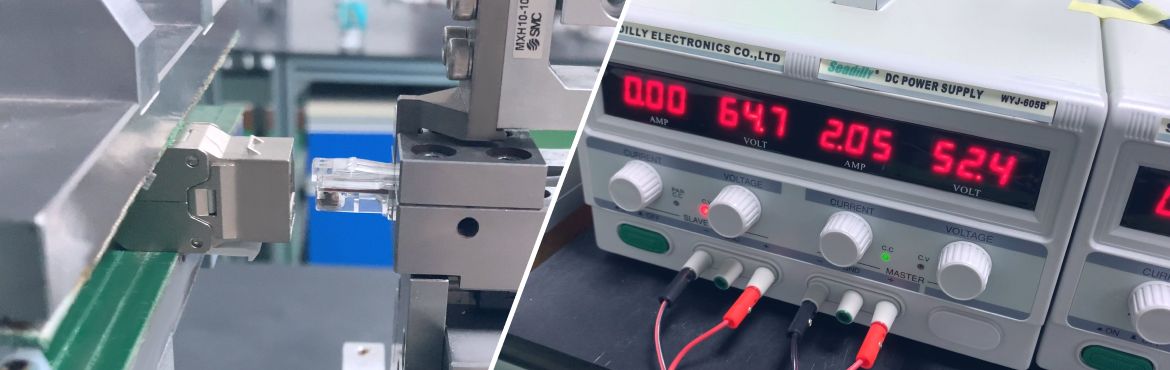
HIPOT Test: PoE RJ45 8P8C Connectors
HIPOT test is an essential procedure for ensuring the quality and safety of connectors. Its primary function is to validate the robustness of the electrical insulation against transient over-voltages. For connector and cable assemblies, the insulation's integrity can be compromised by a variety of factors. These include issues arising from braided shielding, stray wire strands, variations in tolerance, the presence of corrosive impurities, and challenges related to terminal spacing. Furthermore, the insulation may sometimes get damaged, experiencing cuts, or might be inadvertently nicked or compressed during assembly. The Hipot test serves as an efficient method to detect such anomalies, ensuring that the finished PoE connectors maintain their expected performance standards and safety. This rigorous testing guarantees that the end products are both reliable and secure for their intended PoE applications.
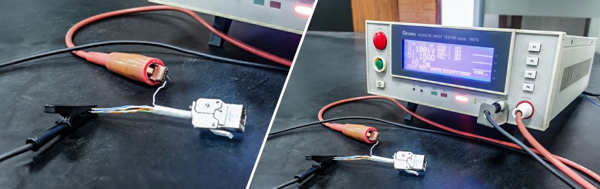
Insulation Resistance Test of PoE RJ45 Connectors
The insulation resistance test is vital for preventing shocks and short circuits, and this test can be done together with the HIPOT tester as shown above. It assesses the insulation's capability to withstand various stresses, including electrical, mechanical (flexing or bending), chemical, temperature fluctuations, oxidation, humidity, aging, and UV light exposure. Typically, this test operates at levels up to 1,000 VDC or 1,500 VDC. When unwanted current flows through the insulator from the conductor, it can lead to serious issues like short circuits, flash arcing, overheating, potential fires, and even electrocution. Thus, testing insulation resistance is essential to ensure safety when the connectors are used for power over Ethernet.
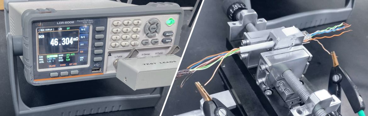
Contact Resistance Test (Milliohm Meter Test) of PoE RJ45 Connectors
Contact resistance is a crucial metric in assessing the efficacy of electrical connections, encompassing aspects like terminations, joints, and connectors. This assessment plays a pivotal role in identifying potential weak points, such as loose connections or specific challenges like contamination affecting contact surfaces and fretting corrosion (caused by gradual wear by means of rubbing between two contacts during plugin and unplugging). Testing this resistance ensures optimal electrical transmission performance and prevents potential failures, which is instrumental in upholding the integrity and reliability of these connections.
Mixed Flowing Gas Testing of PoE RJ45 Connectors
The mixed flowing gas test (also called MFG test) allows us to assess the durability of new electrical contact coatings when exposed to corrosive gasses in test environments. By creating an accelerated environment, mixed flowing gas testing helps pinpoint potential weaknesses (contact resistance and insulation resistance at high voltages). Utilizing these insights, we can minimize early wear and associated risks, ensuring connector reliability and safety.
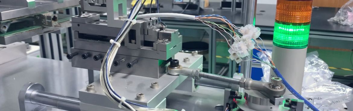
PoE Connector Test Methods (IEC60512-99-002)
The following details the testing procedures for PoE connector safety and performance, adhering to the standards set by IEC60512-99-002. This specific standard caters to connectors used in IEEE 802.3bt. Specifically, it pertains to both Type 3 PoE++ (or 4PPoE) and Type 4 PoE++ (or 4PPoE) RJ45 connectors. The IEC60512-99-002 outlines rigorous criteria to ensure the optimal operation of these connectors, making them both safe and efficient. This standard has been internationally recognized and is critical for maintaining consistency across devices. A demonstration of these testing methods is provided below.

- Related Products
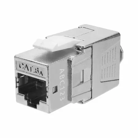
Cat.6A STP Component Level Toolless Keystone Jack
The component level 4PPoE keystone jack has an ID number printed on it. A component test report...
Details Add to List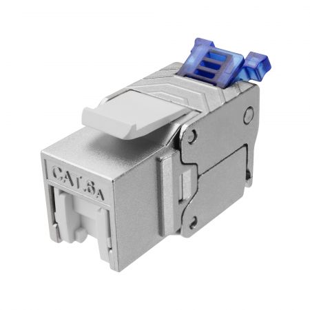
Cat.6A STP 180 Degree Toolless Keystone Jack With Cable Clamp
FORCE certified 4PPoE keystone jack is space-saving and compact for limited space. The Toolless...
Details Add to List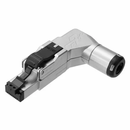
Cat.6A STP 5 Angle Field Termination Plug
The five angled Cat6a field termination plug is applied under 100 meter channel test for datacenter...
Details Add to List
Cat.6A STP Large Diameter Modular Plug
With the EXW patented 3-prong contact blades and its outstanding conductivity, the modular...
Details Add to List- Tool Recommendations

Crimping Plier for RJ45 Toolless Plugs and Keystone Jacks
The unique crimping tool is simple and fast to work with Toolless plugs and jacks. The front...
Details Add to List
RJ45 Multi-Function Crimper
RJ45 crimper and wire cutter for snagless, non-snagless, pass-through, and closed-end plugs...
Details Add to List
Spring-Loaded RJ45 Twisted Pair Network Cable Stripper
The spring-loaded cable stripper for UTP and STP twisted pair network cables is a light, durable,...
Details Add to List- Related FAQ
The quality of each keystone jack, cable, and patch cord is an essential factor that can affect the transmission performance of the channel. So, we test each of our Category 6A Component Level Keystone...
Read moreWe verify our 4PPoE patch cords through Fluke DSX cable analyzer and Fluke LinkIQ cable network analyzer, ensuring the transmission performance and electrical resistance standards for PoE applications....
Read moreThe Modular Plug Terminated Link (MPTL) is a new “direct connect” link model where a horizontal cable is terminated and directly attached to a modular plug or a tool-free field termination plug. MPTL...
Read more