How to Verify 4PPoE Patch Cords Through Channel (+All) Test and Class 8 PoE Test
We verify our 4PPoE patch cords through Fluke DSX cable analyzer and Fluke LinkIQ cable network analyzer, ensuring the transmission performance and electrical resistance standards for PoE applications. Our 4PPoE (PoE++) patch cords are compliant with IEEE 802.3bt Type 4 Class 8, delivering 90W from PSE and 71.3W to PD. The 4PPoE patch cords help you save cost and simplify installation, supporting high-power applications in smart buildings.
How Do We Verify Our 4PPoE Patch Cords?
We test the 4PPoE patch cord in a channel, using Fluke DSX cable analyzer with the Channel (+All) test limit and Fluke LinkIQ cable network tester. We use these two Fluke testers to ensure the transmission performance, the Resistance Unbalance, and the actual wattage at PD, according to the ISO 11801, ANSI/TIA-568.2-D, IEEE 802.3bt Type 4 Class 8 standards.
UTP and STP Channel Configurations for 4PPoE
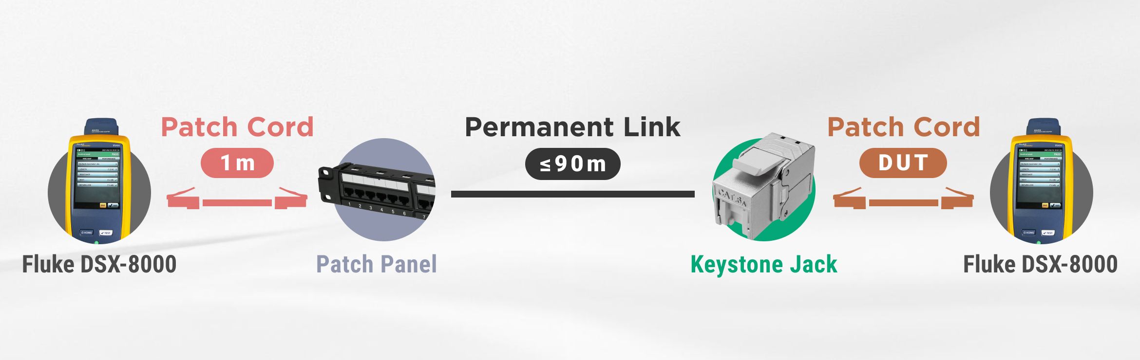
We would set up a UTP or STP channel to test a RJ45 patch cord in a channel. An example of a 26 AWG STP channel is shown below. Our channel would use Cat6A S/FTP 26 AWG patch cord, Cat.6A STP 180 Degree Toolless Keystone Jack With Cable Clamp, and Cat.6A FTP 90 Degree 1U 24 Port Patch Panel. All of the components are compliant to ISO 11801, IEC 60603-7-51, ANSI/TIA-568.2-D, and IEEE 802.2bt Type 4 Class 8 (90W).
Maximum Length IEEE 802.3bt Type 4 Class 8 Patch Cord Run in a Channel
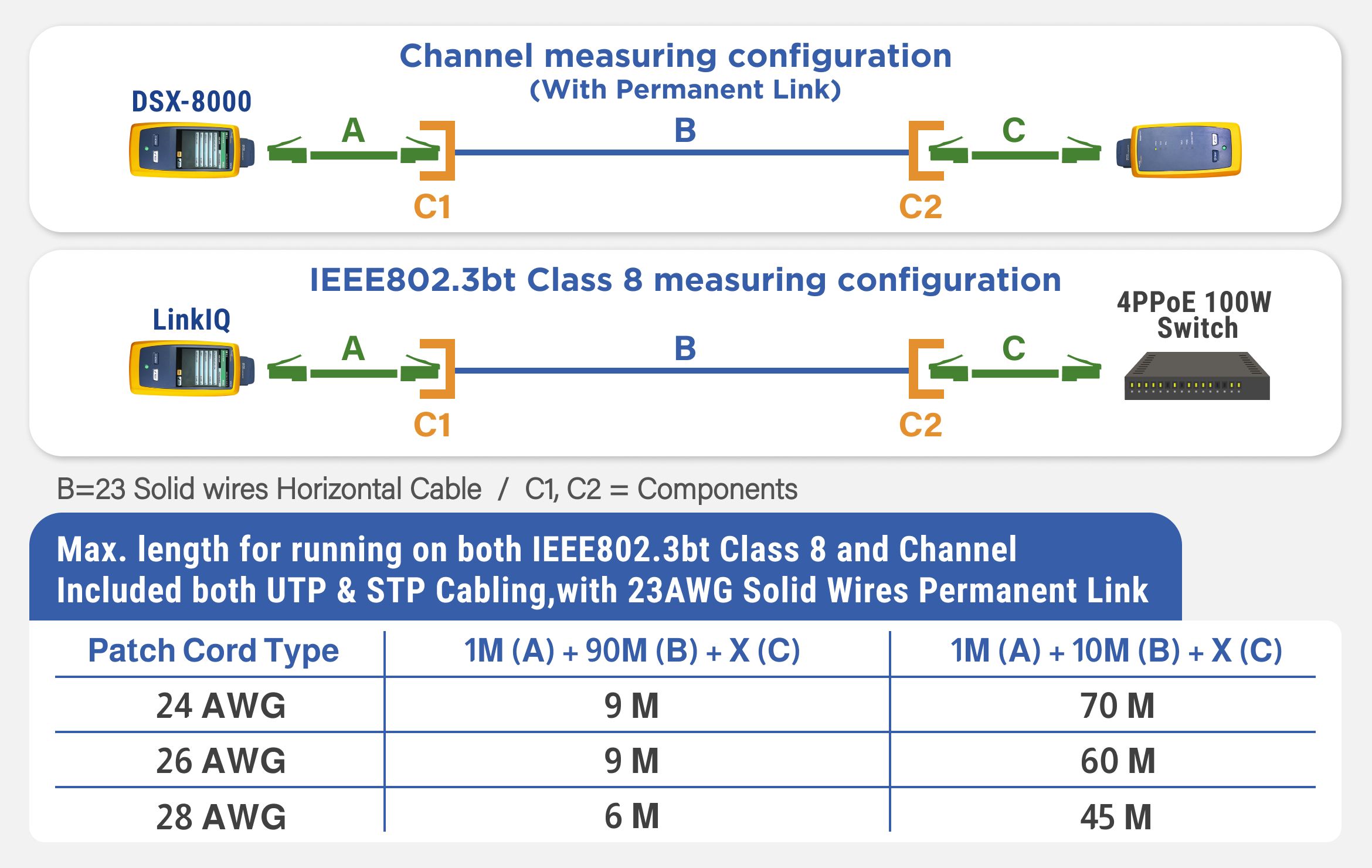
The patch cord's resistance unbalance and length can affect the actual voltage and current reaching the PD. So, it is essential to make sure that the patch cord has an acceptable difference in resistance unbalance and use an acceptable cable length to properly support a PoE installation. The acceptable patch cord lengths in the chart below indicate the recommended maximum lengths for the specific AWG patch cords that passed Channel (+All) transmission performance (tested with our channel) and Class 8 PoE load test. We use two different permanent link lengths (90 meters and 10 meters) for best-case and worst-case scenarios. As you can see in the chart below, we fix Cord A (patch cord) at 1 meter and Cable B (permanent link) at 90 meters or 10 meters, in order to test the maximum length of Cord C (the patch cord under test) in different AWGs. So, the suitable patch cord lengths (Cord C) may vary due to the different AWG sizes as shown below.
Fluke DSX Channel (+All) Test Report
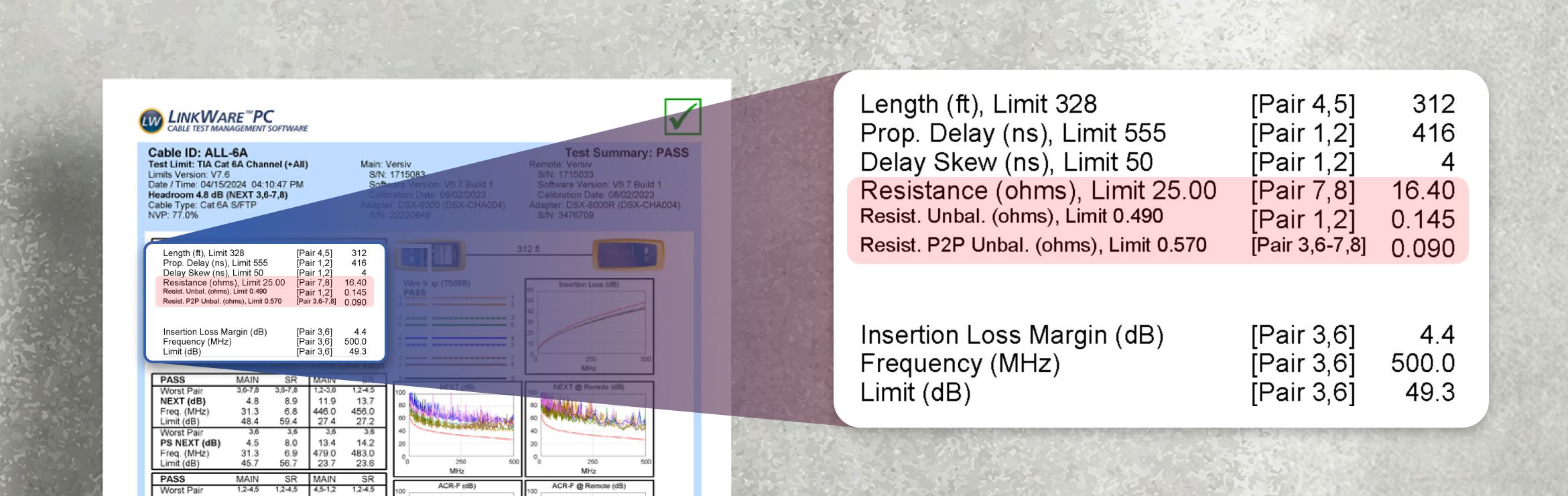
The Fluke DSX Channel (+All) test report includes two significant test values (“Resist. Unbal.” and “Resist. P2P Unbal.”) that we take into account when assessing the PoE of a channel. By verifying the resistance unbalance of the channel with ISO 11801 and ANSI/TIA-568.2-D standards, you can be confident that new cabling installations will function for both data and power delivery. The Fluke DSX test report ensures that the Resistance Unbalance within a pair and between pairs are lower than the limit standards according to ISO and ANSI/TIA.
Resistance Unbalance Test Limits for Category 5e, 6, 6A Channels
The resistance unbalance test limits on a Fluke DSX cable analyzer are configured according to ISO 11801 and TIA-568.2-D. In a Channel (+All) test report for Cat5e, 6, and 6A, the “Resist. Unbal.” (resistance unbalance within a pair) shall not exceed 0.20 Ω or 3%, whichever is greater. The “Resist. P2P Unbal.” (resistance unbalance between pairs) shall not exceed 0.1 Ω or 7%, whichever is greater. For Category 5e, 6, 6A channels or permanent links, ISO 11801 and TIA-568.2-D have the same requirements for the maximum resistance unbalance within each pair and between pairs.
What Is Resistance Unbalance: Two Significant Values for Successful PoE Connections
Resistance unbalance testing is significant to determine the capability of PoE connection in the channel that meets ISO 11801 and IEEE 802.3bt Type 4 Class 8 (90W) standards. We take "Resist. Unbal.” and “Resist. P2P Unbal.” test values into consideration for PoE delivered over the pairs, as shown in the Channel (+All) test report above. "Resist. Unbal.” is the difference in DC resistance (resistance unbalance) between the two conductors within a pair. “Resist. P2P Unbal.” is the difference between pairs.
Possible Causes of Resistance Unbalance in RJ45 Patch Cords
The primary causes of resistance unbalance in patch cords include the use of non-pure bare copper conductors, substandard manufacturing processes, incorrect termination tools, and poor installation practices. These causes can impair a patch cord’s ability to efficiently carry power and data to a PD. Resistance variance within and between wire pairs can arise from factors such as manufacturing inconsistencies, excessive cable length use, physical damage to cables, bending the cable beyond its specified bend radius, and inconsistent termination (such as using inappropriate tools or failing to maintain the twist of the pairs close to the termination points), and the use of lower quality cables (e.g. copper-clad aluminum (CCA) cables that do not meet ISO, ANSI/TIA, and UL standards due to their higher DC resistance unbalance).
Why Is Resistance Unbalance Important to PoE Installations?
High resistance unbalance can cause issues like voltage imbalances, insufficient power to devices, overheating, and data transmission errors. Severe resistance unbalance can cause the PoE to stop working altogether, as the PD might not receive the required power wattage consistently. This may result in some wires carrying more current than designed, leading to voltage imbalances, overheating, and device failure. To ensure PoE, all RJ45 copper channel components—such as solid horizontal cables, keystone jacks, patch panels, and stranded patch cords, plugs—must meet specific resistance unbalance standards (we will go into the acceptable resistance unbalance values and percentages of a channel later).
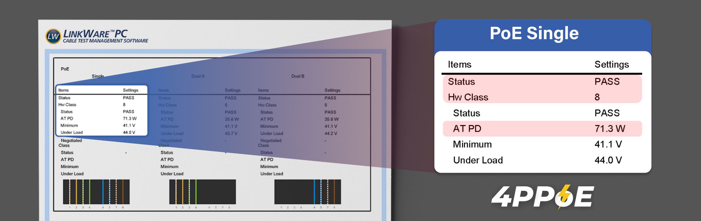
Fluke LinkIQ Class 8 PoE Test Report
The LinkIQ PoE test is a straight-forward field testing, with actual wattage reaching the PD and the hardware class (Hw Class 8) that indicates power from the PSE. After testing the transmission and resistance of our patch cords by Fluke DSX, we use Fluke LinkIQ to field-test the actual PoE wattage to LinkIQ under a 90 W load granted by an IEEE 802.2bt switch. We identify the maximum length that patch cords can support for data and power transmission when connected to the 90W switch. By doing Channel (+All) and LinkIQ testing, we ensure our patch cords are compliant to IEEE 802.3bt Type 4 Class 8, ISO 11801, and ANSI/TIA 568.2-D.
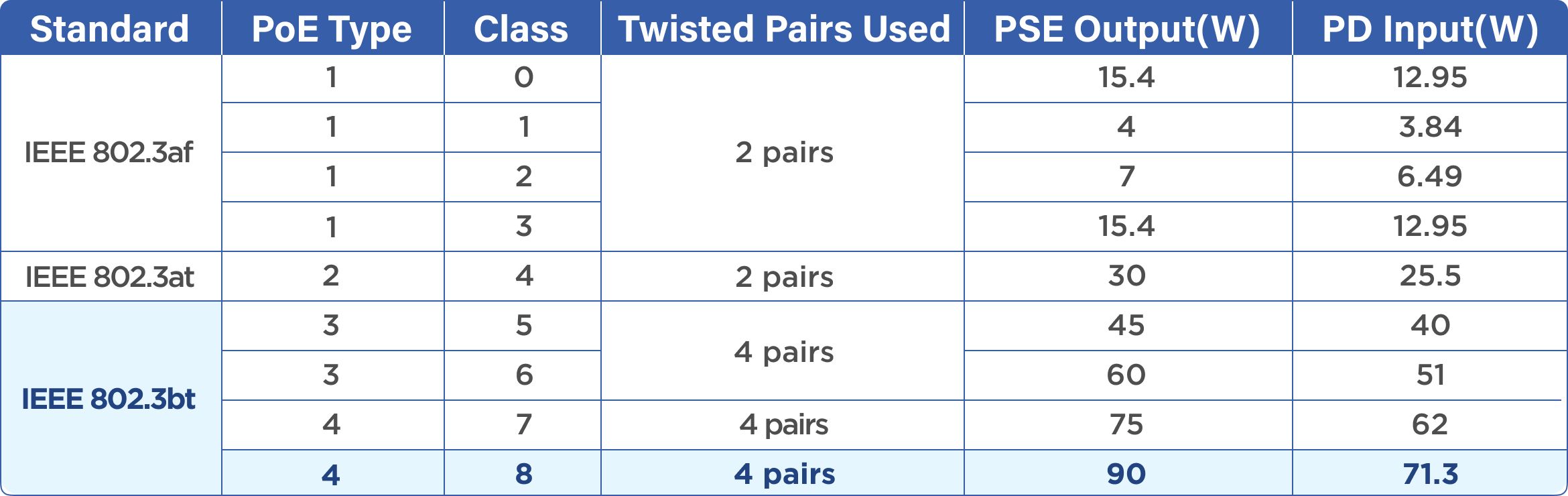
We Provide The Highest PoE standard Patch Cords
PoE standards range from PoE (class 0) to 4PPoE (class 8), supplying from 15.4W to 90W. We provide 24AWG, 26AWG, 28AWG UTP and STP patch cords in Cat5E, Cat6, and Cat6A that undergo the highest PoE load test (IEEE 802.3bt Type 4 Class 8). Our 4PPoE (PoE++) patch cords can support 90 W from the PSE and 71.3 W to the PD, providing an efficient and economical solution to connect devices with the 4PPoE patch cords.
What Are The benefits of 4PPoE Patch Cords?
4PPoE (PoE++) patch cords supply data and power over a single patch cord, so you can simplify network infrastructure and enhance flexibility. Without the need for additional power cords, 4PPoE patch cords reduce the amount of required cabling, leading to a more efficient use of spaces. In addition, using PoE patch cords makes it easier to move, add, and change the components in your structured cabling systems. With this flexibility, technicians and engineers can also reduce the installation complexity and cost.
4PPoE Patch Cords Applications
4PPoE patch cables are suitable for connecting devices like IP cameras, VoIP phones, wireless access points, PoE 4K TV, PTZ cameras, and digital signages. We ensure IEEE 802.3bt Class 8 PoE over our patch cords, allowing for more flexible applications in smart buildings. For the networking infrastructure in schools, companies, hospitals, and factories, 4PPoE patch cords can deliver at least 71.3W power to PD with 100 MHz for Cat5e, 250 MHz for Cat6, and 500 MHz for Cat6A.

- Related Products
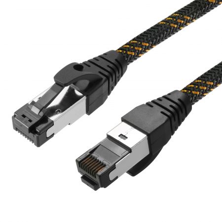
Cat.6A S/FTP 26 AWG Braided Patch Cord
The RJ45 braided ethernet patch cord is built with excellent quality, verified by the Category...
Details Add to List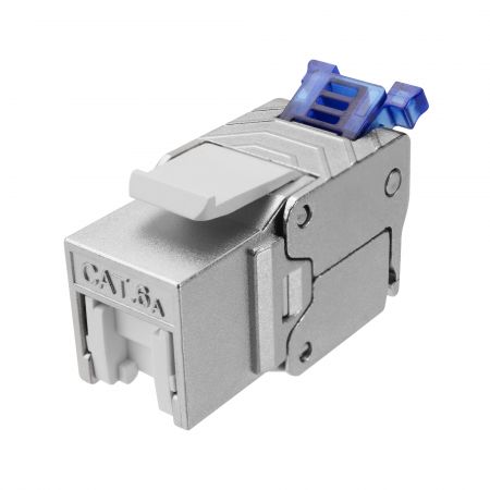
Cat.6A STP 180 Degree Toolless Keystone Jack With Cable Clamp
FORCE certified 4PPoE keystone jack is space-saving and compact for limited space. The Toolless...
Details Add to List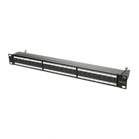
STP 90 Degree 1U 24 Port RJ45 Patch Panel
This 90-degree STP RJ45 patch panel supports Cat6A and Cat6 installations, effectively reducing...
Details Add to List- Tool Recommendations

RJ45 Multi-Function Crimper
RJ45 crimper and wire cutter for snagless, non-snagless, pass-through, and closed-end plugs...
Details Add to List
Flush Cutter for Soft Metal Wires Up to 18 AWG
The flush cutter snips wires up to 18 AWG. It also cuts 1 mm soft metal wires such as copper...
Details Add to List- Related FAQ
The sparking test (also called arcing test) assesses the connector's ability to handle electrical arcs which might occur when connecting or disconnecting under load. An electrical arc is a visible glow...
Read moreThe Modular Plug Terminated Link (MPTL) is a new “direct connect” link model where a horizontal cable is terminated and directly attached to a modular plug or a tool-free field termination plug. MPTL...
Read moreAll of EXW patch cords use pure bare copper wires. EXW patch cords do not use CCA (copper clad aluminum) wires nor do we recommend using patch cords made of CCA wires. In fact, aluminum network cables...
Read more